

Severe abrasion knife gate valves




Purging valves
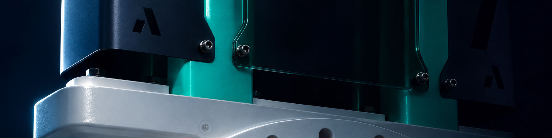
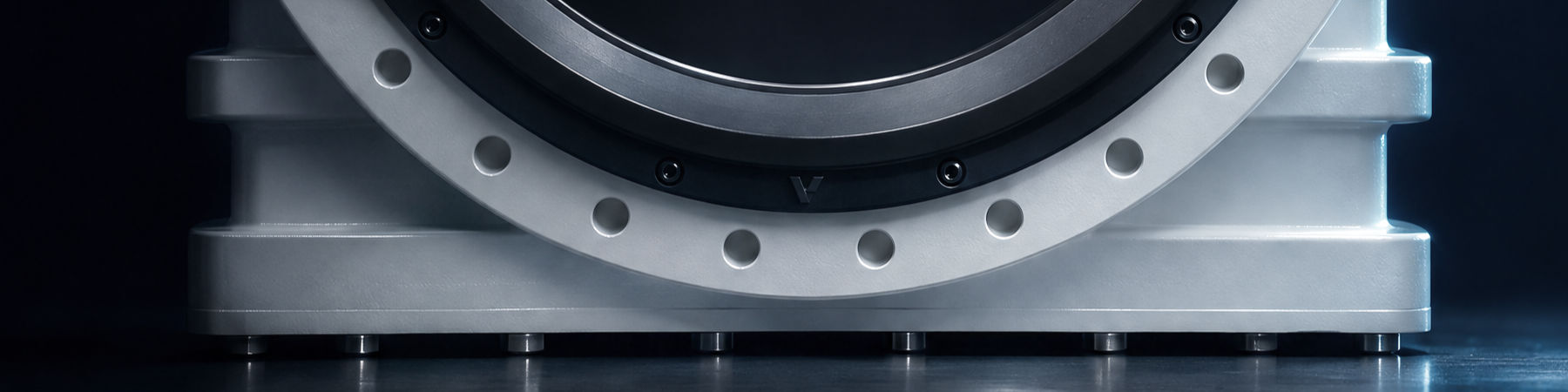
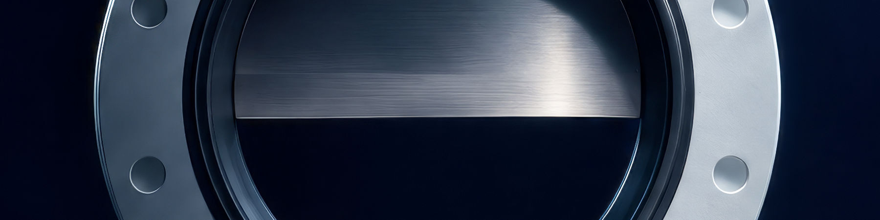
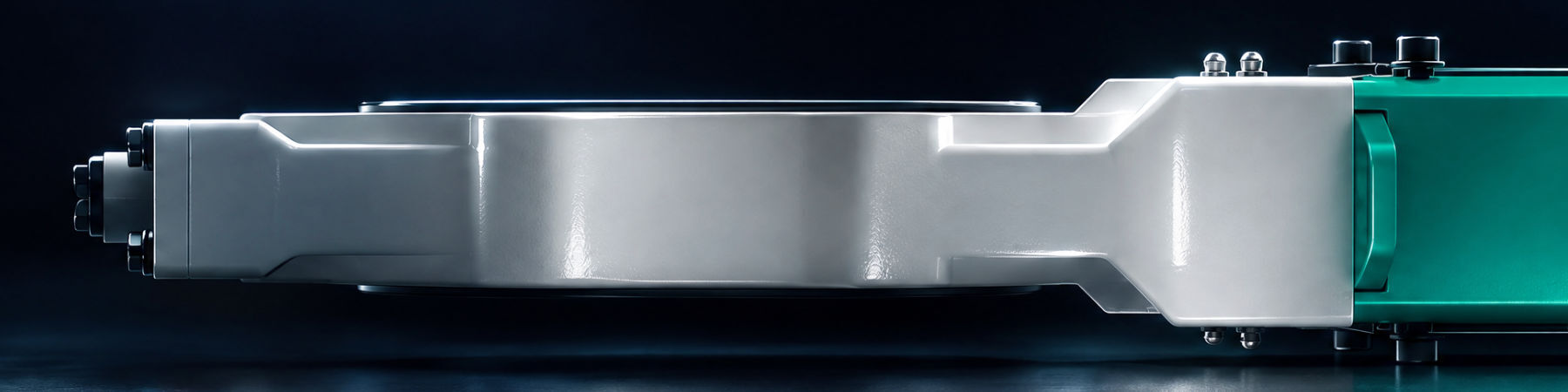
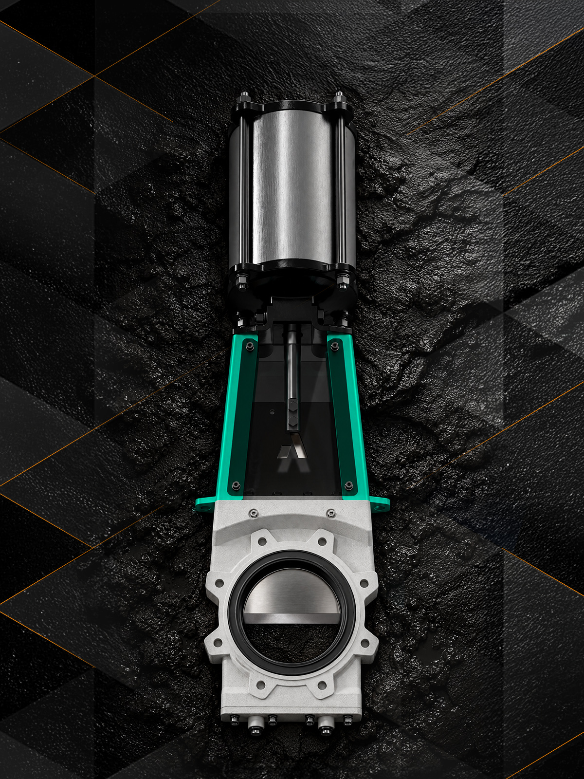
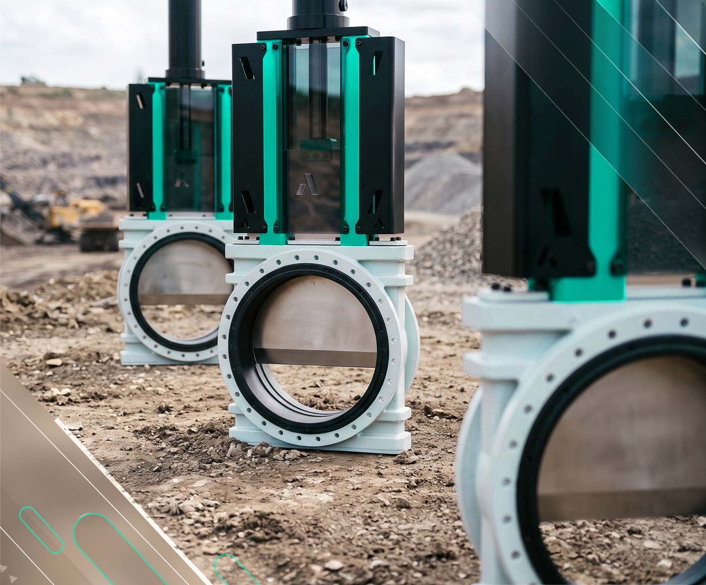
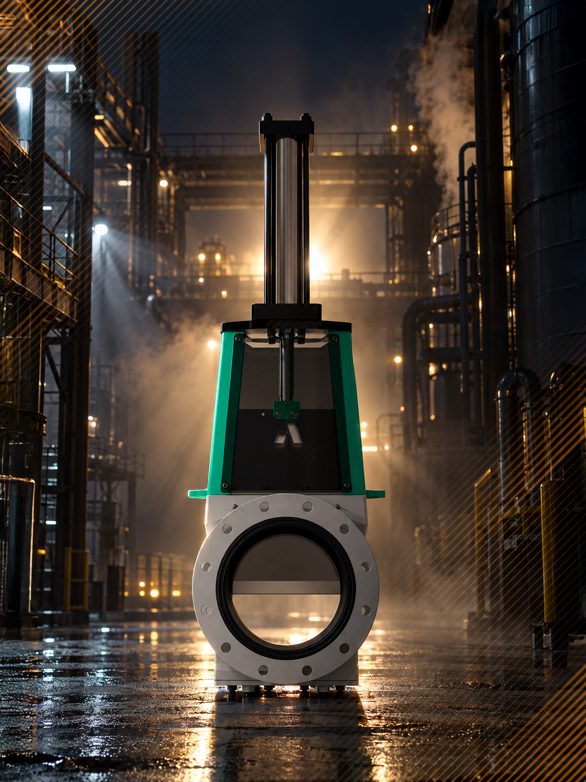
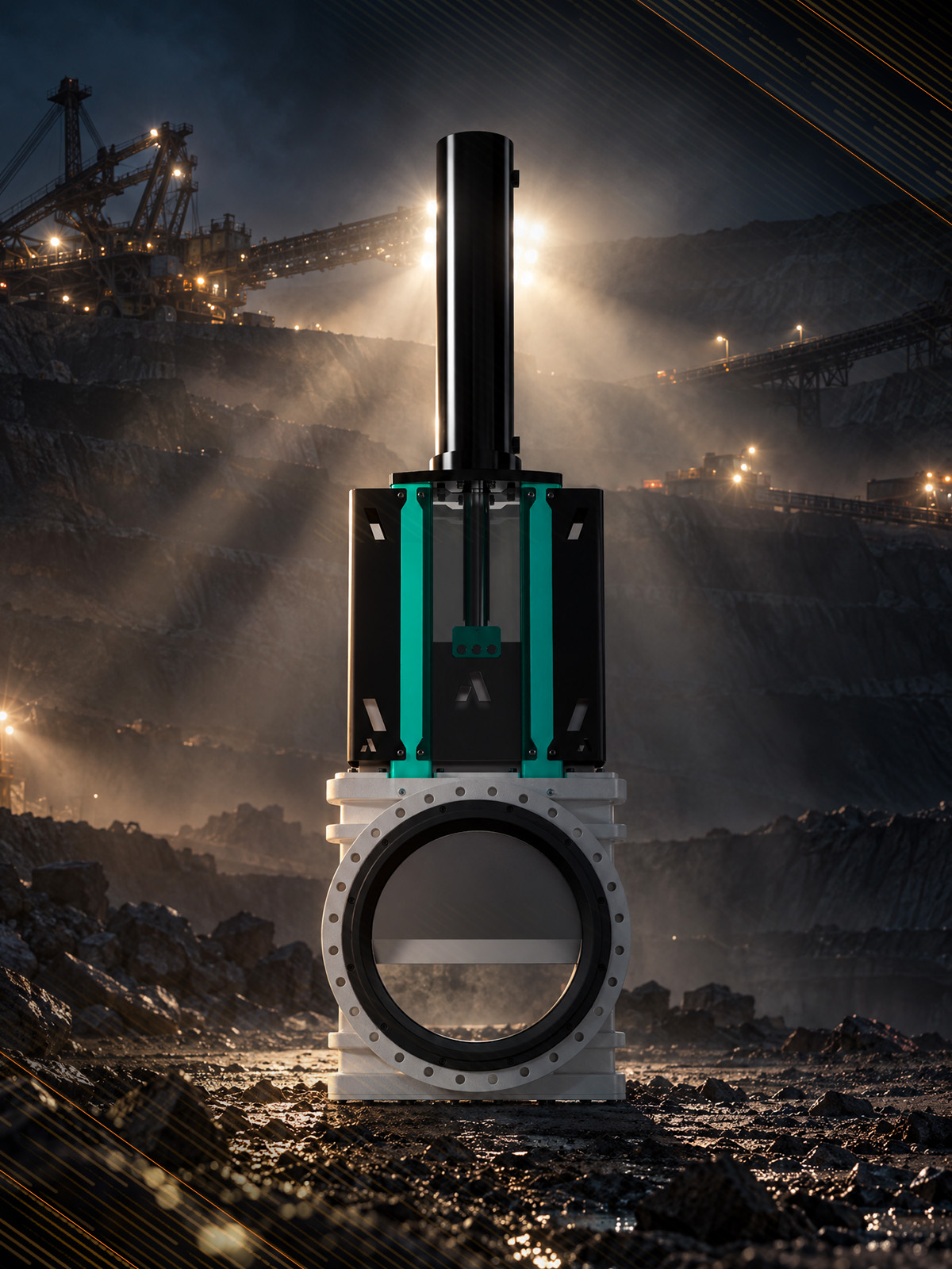
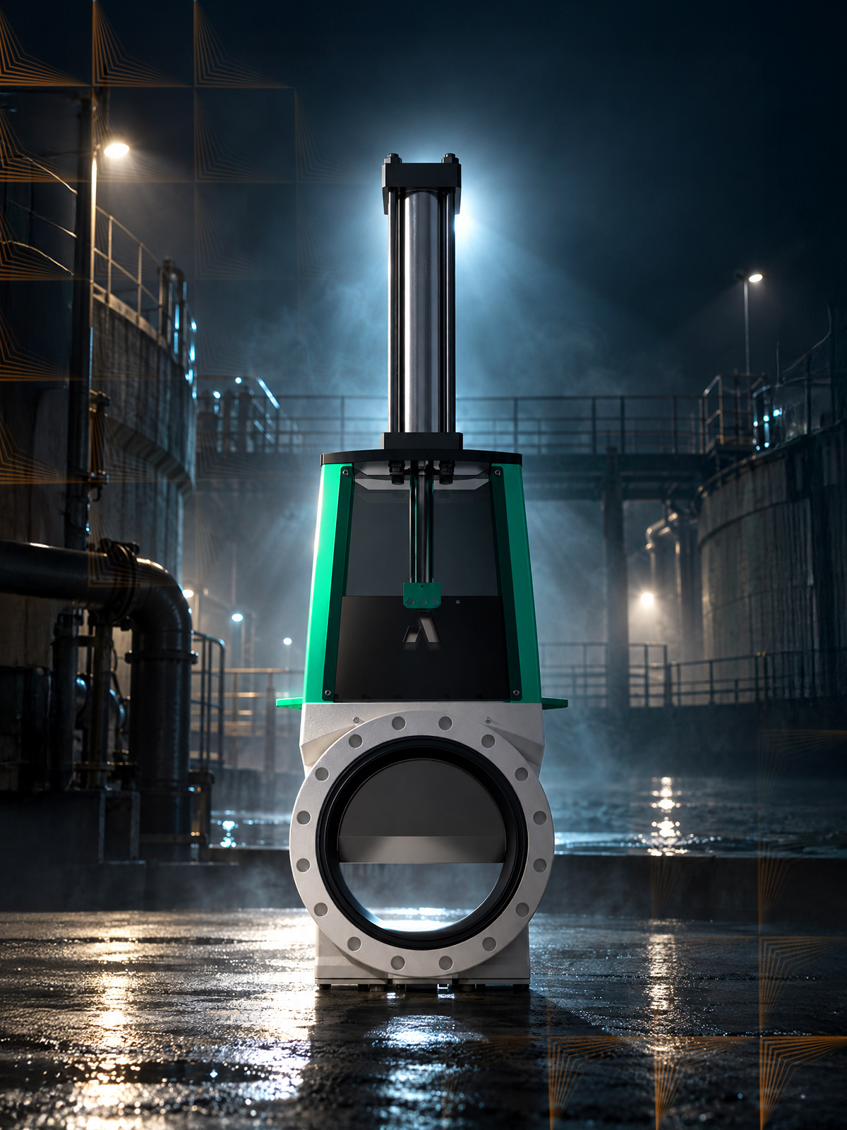
The Arnett Valve FLUX series pushes the media through. Two sleeves meet in the bore centreline and seal the body cavity away from the process. Every stroke pushes the media clear of the seat.
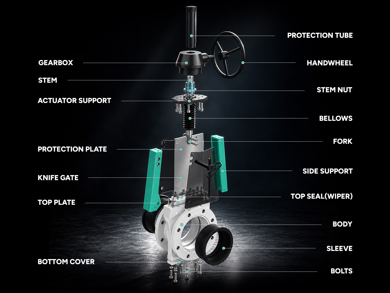

Shared across all four models
| Component | Standard | Optional |
|---|---|---|
| Body | GJS500 ductile iron | WCB carbon steel, CF8M (316) |
| Knife / Gate | SS316 | 17-4 PH, Duplex, Super duplex |
| Sleeve / Seat | NR natural rubber | NBR, EPDM, PU, FKM Viton, AFLAS |
| Top seal (wiper) | NBR nitrile | EPDM, PU, FKM Viton |
| Bottom Joint | NBR nitrile | EPDM, FKM Viton |
| Stem | SS304 | SS316, SS410, Duplex |
| Stem Nut | Bronze | – |
| Fasteners | A2/70 (304 stainless) | A4/70 (316 stainless) |
| Protection Plate | PVC | Carbon steel, SS304, SS316 |

Temperature rating
| Sleeve compound | Continuous service | Best for |
|---|---|---|
| NR natural rubber (standard) | -40°F to 194°F | Abrasion, impact, wet slurry |
| NBR nitrile | -22°F to 212°F | Oily and fatty media |
| EPDM | -40°F to 275°F | Hot water, dilute chemicals |
| PU polyurethane | -30°F to 175°F | Sharp-particle abrasion, fine solids |
| FKM Viton | -15°F to 392°F | High temperature, aggressive chemicals |
| AFLAS | +25°F to 435°F | High temperature plus hot amines, steam |
Available actuators
| Actuator type | Size range | Power source |
|---|---|---|
| Handwheel (direct) | 2”- 8” | Manual |
| Bevel Gearbox | 6” and above | Manual |
| Electric | Standard through 24”. Larger sizes per project. | Electric |
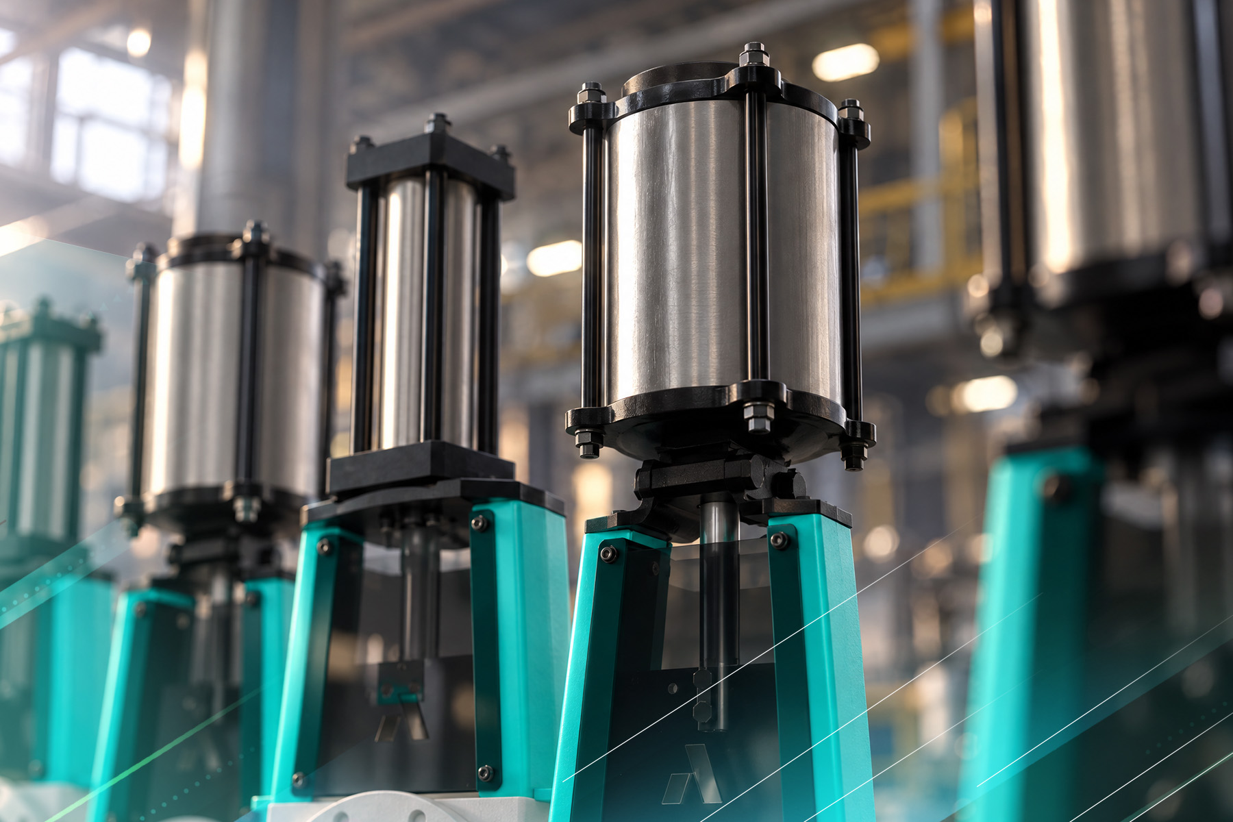
| Pneumatic cylinder (single-acting) | 2”- 16”, custom, consult Arnett | Compressed air |
| Pneumatic cylinder (double-acting) | Standard through 24”. Larger sizes per project. | Compressed air |
| Hydraulic cylinder | Standard through 24”. Larger sizes per project. | Hydraulic |
| Chain wheel | 2”- 6” | Manual |

Applications
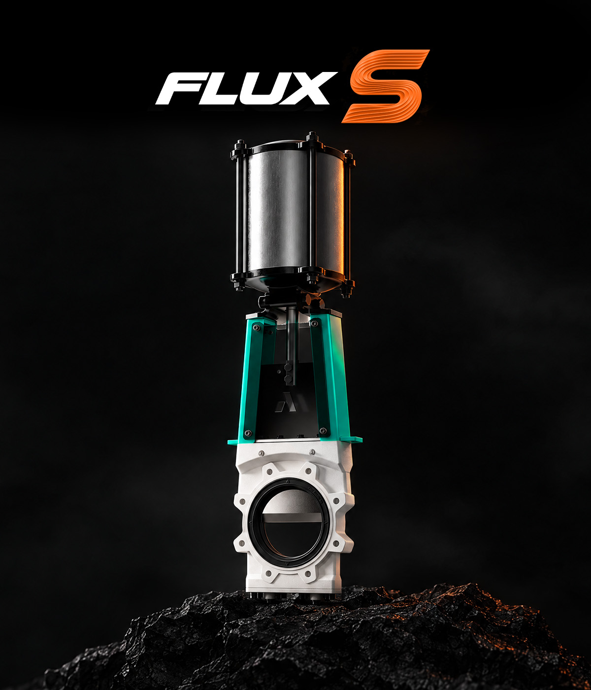
Standard push-through knife gate
The workhorse of the FLUX series.
Compact MSS SP-81 aligned lay length drops into standard knife gate spool spacing. Direct replacement for existing short-pattern knife gates. The pipework stays exactly as it is.
2” through 48” from stock patterns, with larger sizes engineered to order. One valve series covers the plant from mill discharge to main tailings lines.
Shortest body, lightest casting, lowest installed weight of the four models. Where pressure stays inside the standard curve, FLUX S is the cost-of-ownership pick.
General slurry isolation, standard spool spacing, pressures within the standard curve: 150 psi to 24”, 115 psi to 36”, 90 psi to 60”.

FLUX S technical data
| NPS | Face-to-face | Overall height | ISO 5210 |
|---|---|---|---|
| 2” | 2.1” | 10.2” | F07 |
| 2-1/2” * | 2.1” | – | – |
| 3” | 2.2” | 12.2” | F07 |
| 4” | 2.2” | 13.4” | F07 |
| 5” * | 2.5” | – | – |
| 6” | 2.5” | 16.9” | F07 |
| 8” | 3.0” | 20.9” | F10 |
| 10” | 3.0” | 23.4” | F10 |
| 12” | 3.3” | 28.0” | F10 |
| 14” | 3.3” | 31.5” | F10-F14 |
| 16” | 3.8” | 34.8” | F10-F14 |
| 18” | 3.8” | 38.6” | F10-F14 |
| 20” | 4.8” | 41.7” | F14-F16 |
| 24” | 4.8” | 48.0” | F14-F16 |
| 28” * | 7.2” | – | – |
| 30” * | 7.4” | – | – |
| 32” * | 8.1” | – | – |
| 36” * | 8.9” | – | – |
| 40” * | 9.4” | – | – |
| 44” * | 9.4” | – | – |
| 48” * | 10.0” | – | – |
* = made to order. Overall height and ISO 5210 published for standard sizes. Custom flange drilling to fit any requirement. AS 2129 Table D and E available. Hydrostatic test per API 598, shell at 1.5x design pressure, seat at 1.1x design pressure.
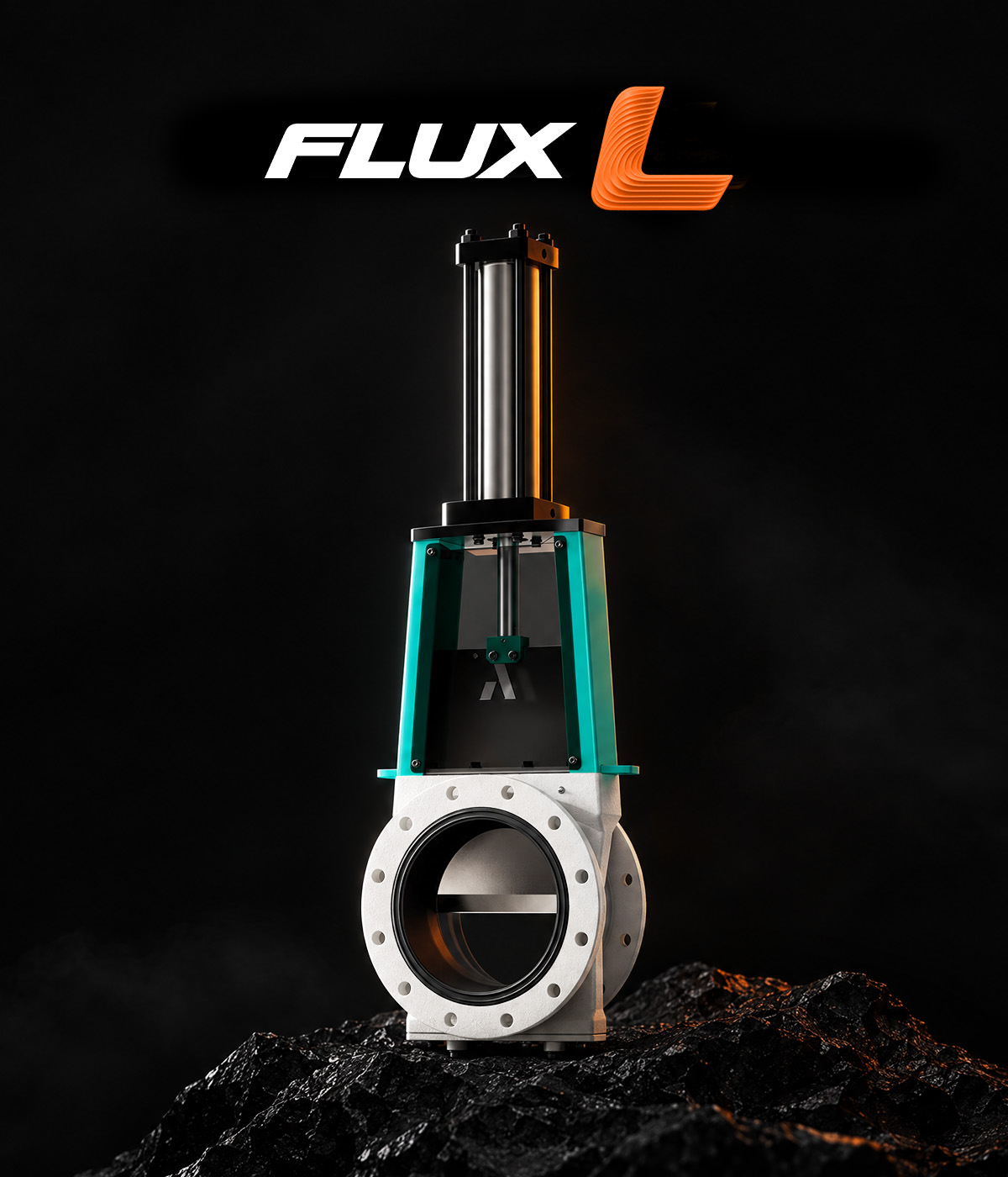
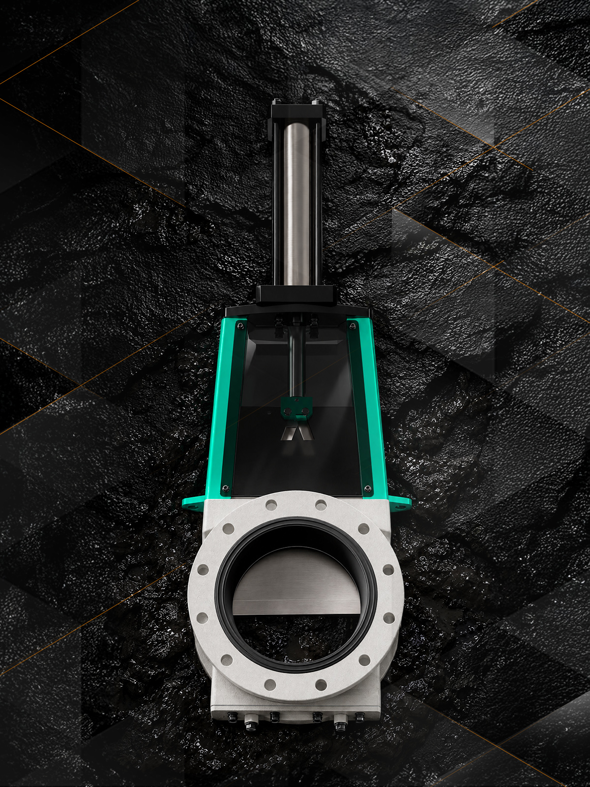
Long pattern push-through knife gate
The same valve, built long.
Same wetted internals, same pressure curve, same materials as FLUX S, in a long-pattern body. Face-to-face runs 6.9” at 2” up to 21.1” at 48”.
Replaces long-pattern gate valves and through-conduit valves in the existing spool. The pipeline dimension drives the choice, the slurry performance stays identical.
Pressure rating, elastomer options, actuation range and applications carry over one to one from FLUX S. Selecting FLUX L is purely a piping decision. The performance carries over whole.
The spool or specification calls for long-pattern face-to-face, or when replacing an existing long-pattern valve like for like.

FLUX L technical data
| NPS | Face-to-face | Overall height | ISO 5210 |
|---|---|---|---|
| 2” | 6.9” | 10.2” | F07 |
| 2-1/2” * | 6.9” | – | – |
| 3” | 6.9” | 12.2” | F07 |
| 4” | 6.9” | 13.4” | F07 |
| 5” * | 7.0” | – | – |
| 6” | 7.0” | 16.9” | F07 |
| 8” | 7.3” | 20.9” | F10 |
| 10” | 8.9” | 23.4” | F10 |
| 12” | 10.2” | 28.0” | F10 |
| 14” | 10.2” | 31.5” | F10-F14 |
| 16” | 11.0” | 34.8” | F10-F14 |
| 18” | 12.6” | 38.6” | F10-F14 |
| 20” | 14.4” | 41.7” | F14-F16 |
| 24” | 14.6” | 48.0” | F14-F16 |
| 28” * | 14.9” | – | – |
| 30” * | 14.9” | – | – |
| 32” * | 15.6” | – | – |
| 36” * | 16.2” | – | – |
| 40” * | 21.0” | – | – |
| 44” * | 21.0” | – | – |
| 48” * | 21.1” | – | – |
* = made to order. Overall height and ISO 5210 published for standard sizes. Custom flange drilling to fit any requirement. AS 2129 Table D and E available. Hydrostatic test per API 598, shell at 1.5x design pressure, seat at 1.1x design pressure.
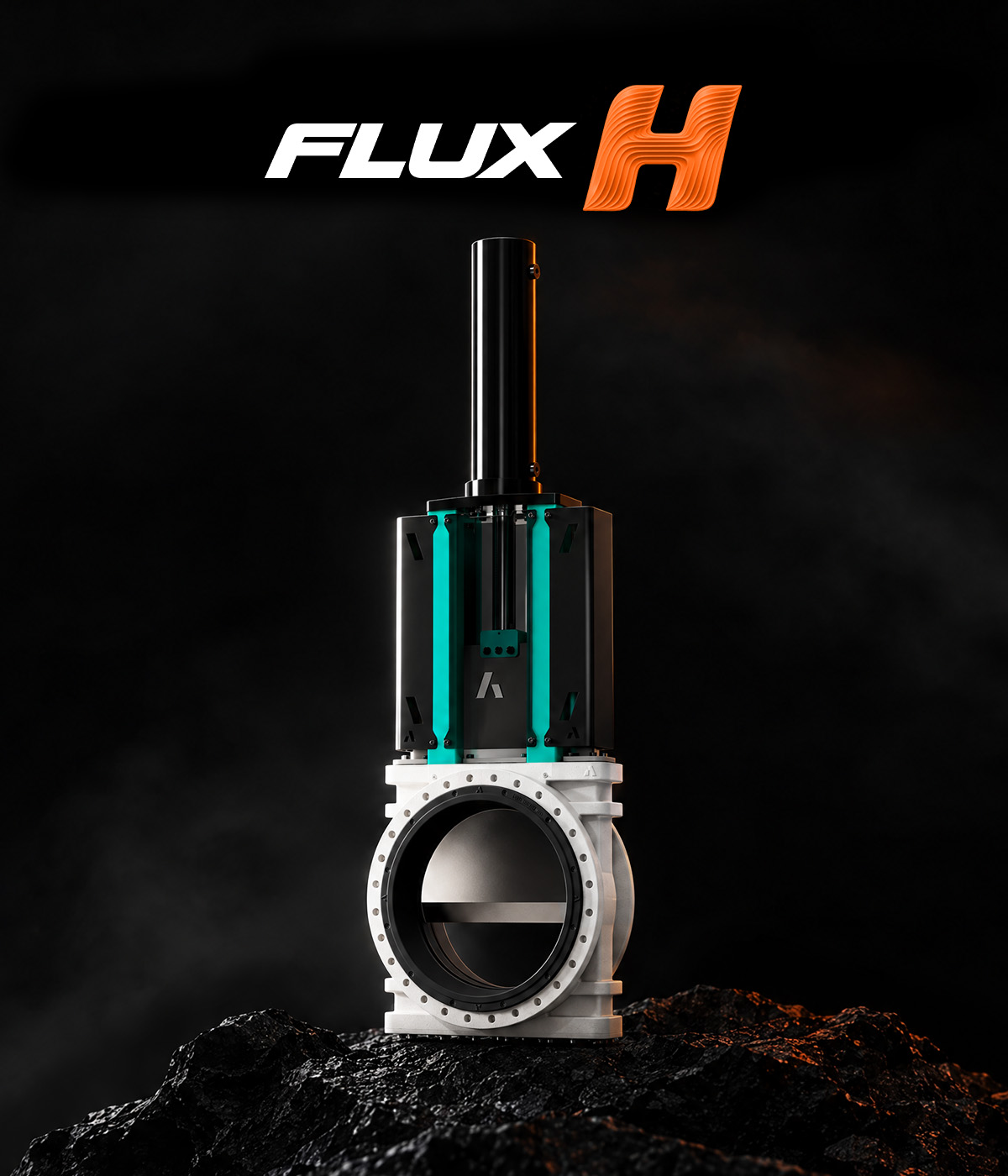
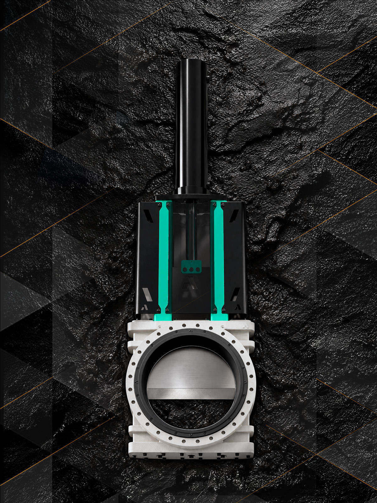
High pressure push-through knife gate
The standard internals.
Thicker body sections and long-pattern face-to-face carry the working pressure to 435 psi across the full size range, with the same push-through sealing concept and the same replaceable sleeves as the standard valve.
Drilled for ANSI Class 150 and Class 300 patterns, with EN 1092 PN options for metric installations. The valve matches the flange class the high-pressure line already carries.
The sleeve remains the only consumable. High pressure service on the same spares list and the same maintenance procedures.
Discharge lines, cyclone feed, higher static head, or any slurry duty where the standard curve tops out but the media and maintenance profile stay the same.

FLUX H technical data
| NPS | Face-to-face | Overall height | ISO 5210 |
|---|---|---|---|
| 2” | 6.9” | 10.6” | F07 |
| 2-1/2” * | 6.9” | – | – |
| 3” | 6.9” | 12.6” | F07 |
| 4” | 6.9” | 13.2” | F07 |
| 5” * | 7.0” | – | – |
| 6” | 7.0” | 17.5” | F10-F14 |
| 8” | 7.3” | 21.7” | F10-F14 |
| 10” | 8.9” | 24.4” | F10-F14 |
| 12” | 10.2” | 28.7” | F14 |
| 14” | 10.2” | 32.5” | F14 |
| 16” | 11.0” | 36.2” | F14 |
| 18” | 12.6” | 39.8” | F14-F16 |
| 20” | 14.4” | 44.1” | F14-F16 |
| 24” | 14.6” | 50.8” | F16-F25 |
| 28” * | 14.9” | – | – |
| 30” * | 14.9” | – | – |
| 32” * | 15.6” | – | – |
| 36” * | 16.2” | – | – |
| 40” * | 21.0” | – | – |
| 44” * | 21.0” | – | – |
| 48” * | 21.1” | – | – |
* = made to order. Overall height and ISO 5210 published for standard sizes. Custom flange drilling to fit any requirement. AS 2129 Table D and E available. Hydrostatic test per API 598, shell at 1.5x design pressure, seat at 1.1x design pressure.
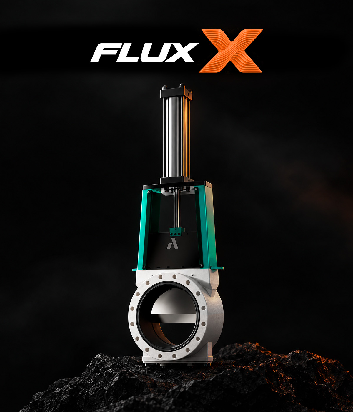
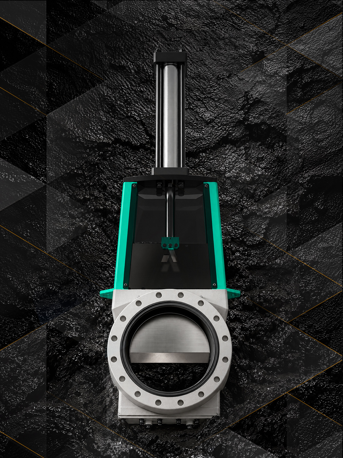
Extreme pressure push-through knife gate
Push-through sealing.
The heaviest casting in the series carries 725 psi working pressure while keeping the full-port push-through geometry. Slurry isolation at pressures that traditionally forced a switch to metal-seated valves and their abrasion penalty.
Drilled for ANSI Class 300, with EN 1092 high-pressure PN patterns for metric installations, matching the flange rating of high-pressure slurry pipelines.
Wear renewal is still a snap-in sleeve on site. At a pressure class where the alternative consumable is a machined metal assembly, here it is a snap-in elastomer sleeve.
Long-distance tailings and pipeline transport, high-head pump discharge, autoclave and pressure-let-down circuits, or wherever the line rating exceeds FLUX H. Sizes above 24” engineered to order.

FLUX X technical data
| NPS | Face-to-face | Overall height | ISO 5210 |
|---|---|---|---|
| 2” | 6.9” | 11.0” | F10 |
| 2-1/2” * | 6.9” | – | – |
| 3” | 6.9” | 13.0” | F10 |
| 4” | 6.9” | 14.4” | F10 |
| 5” * | 7.0” | – | – |
| 6” | 7.0” | 18.1” | F10 |
| 8” | 7.3” | 22.4” | F14 |
| 10” | 8.9” | 25.0” | F14 |
| 12” | 10.2” | 29.5” | F16 |
| 14” | 10.2” | 33.5” | F16 |
| 16” | 11.0” | 37.0” | F25 |
| 18” | 12.6” | 40.6” | F25 |
| 20” | 14.4” | 44.9” | F30 |
| 24” | 14.6” | 52.4” | F30 |
* = made to order. Overall height and ISO 5210 published for standard sizes. Custom flange drilling to fit any requirement. AS 2129 Table D and E available. Hydrostatic test per API 598, shell at 1.5x design pressure, seat at 1.1x design pressure.
Choose the variant
| FLUX S | FLUX L | FLUX H | FLUX X | |
|---|---|---|---|---|
| Working pressure | 150 psi to 24” | 150 psi to 24” | 435 psi | 725 psi |
| Sizes | 2” to 48” | 2” to 48” | 2” to 48” | 2” to 24” |
| Face-to-face | 2.1” to 10.0” | 6.9” to 21.1” | 6.9” to 21.1” | 6.9” to 14.6” |
| Overall height at 24” | 48.0” | 48.0” | 50.8” | 52.4” |
| Flange platform | ANSI 150 | ANSI 150 | ANSI 150, ANSI 300 | ANSI 300 |
| Shut-off | Bidirectional drop-tight | Bidirectional drop-tight | Bidirectional drop-tight | Bidirectional drop-tight |

Contact Arnett
Call, send an email or fill in the form. An Arnett engineer replies with a quote and a recommended model.